Solution
Empowering Next-Generation AI and Data Centers

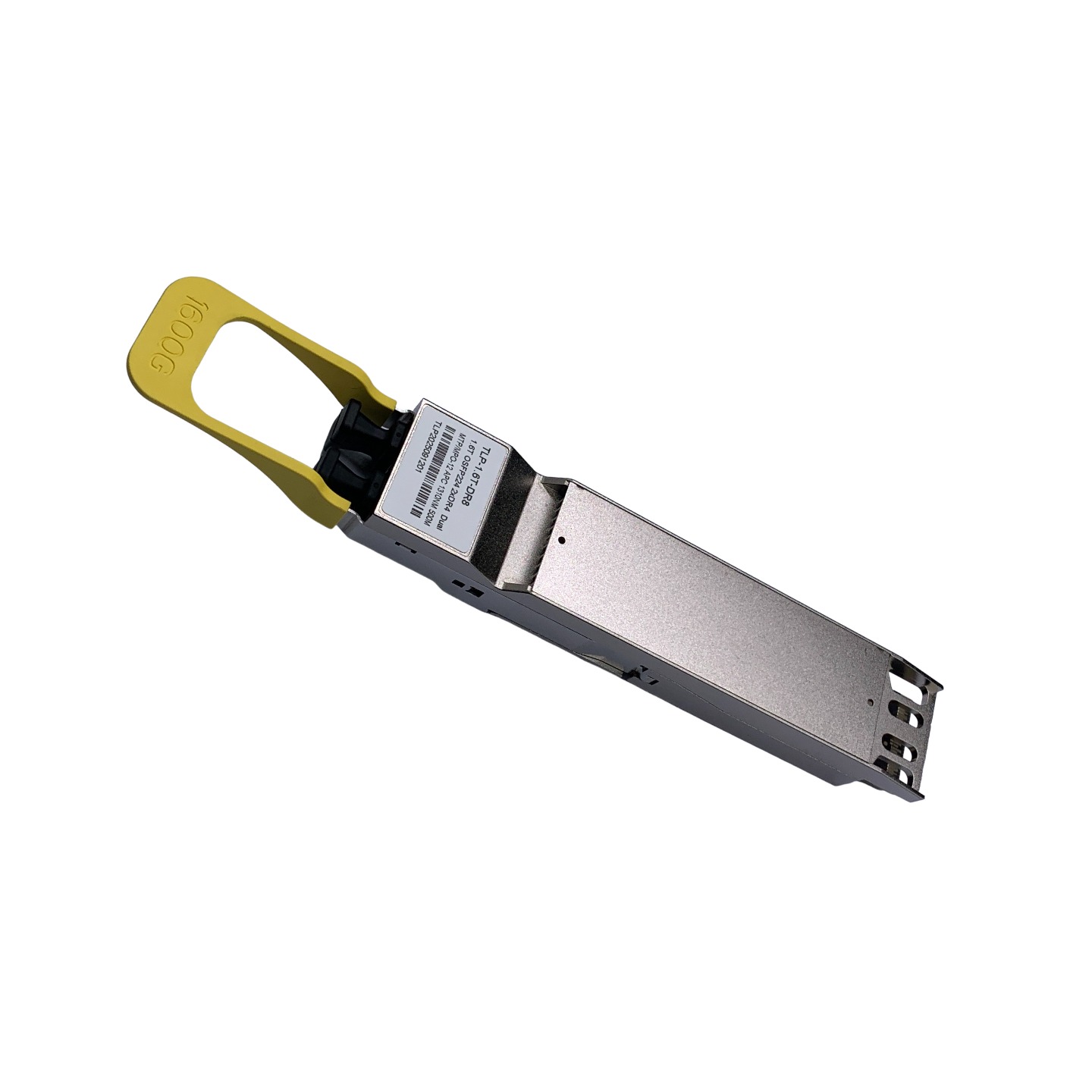
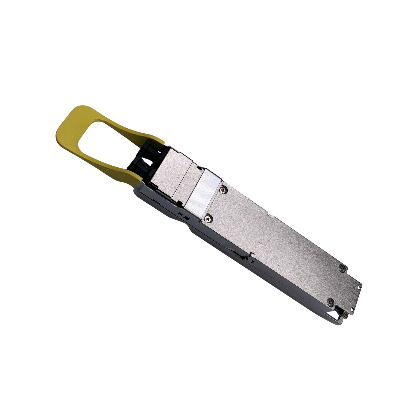
Built-in Broadcom 3nm DSP
Supporting 1.6T to 2x800G NIC Connectivity
Maximum power consumption ≤25W
8x200G-PAM4 electrical modulation
Compliant with OSFP MSA, IEEE 802.3dj_D1.1 protocol and CMIS 5.2.
Scheme Design
Industry-standard approach using an edge-coupled external light source combined with solid waveguides — a unified optical design that scales across 200G, 400G, 800G and 1.6T product families.
Single-source 1:4 and 1:8 fan-out designs, including FR-4 compatible options, to shorten development cycles and simplify integration.
Unique in-module coupling, locking mechanisms and high/low-temperature compensation algorithms that establish the foundation for high yield, low-cost mass productions.
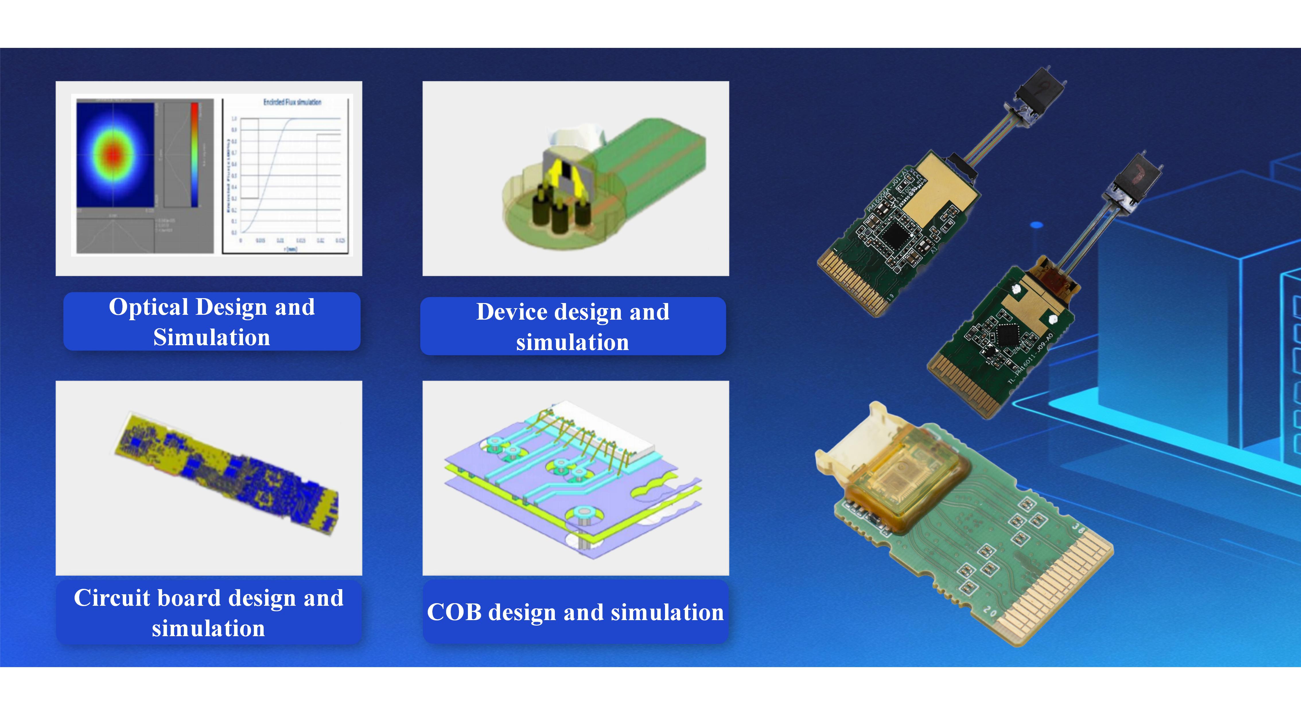
Simulation Analysis
End-to-end simulation and analysis: full optical-path optical simulation, thermal simulation, signal-integrity (SI) simulation and 3D structural analysis.
Engineering platform supports the productization of all-silicon-photonics solutions from 200G through 1.6T.
79 granted patents specifically for silicon-photonic solutions.
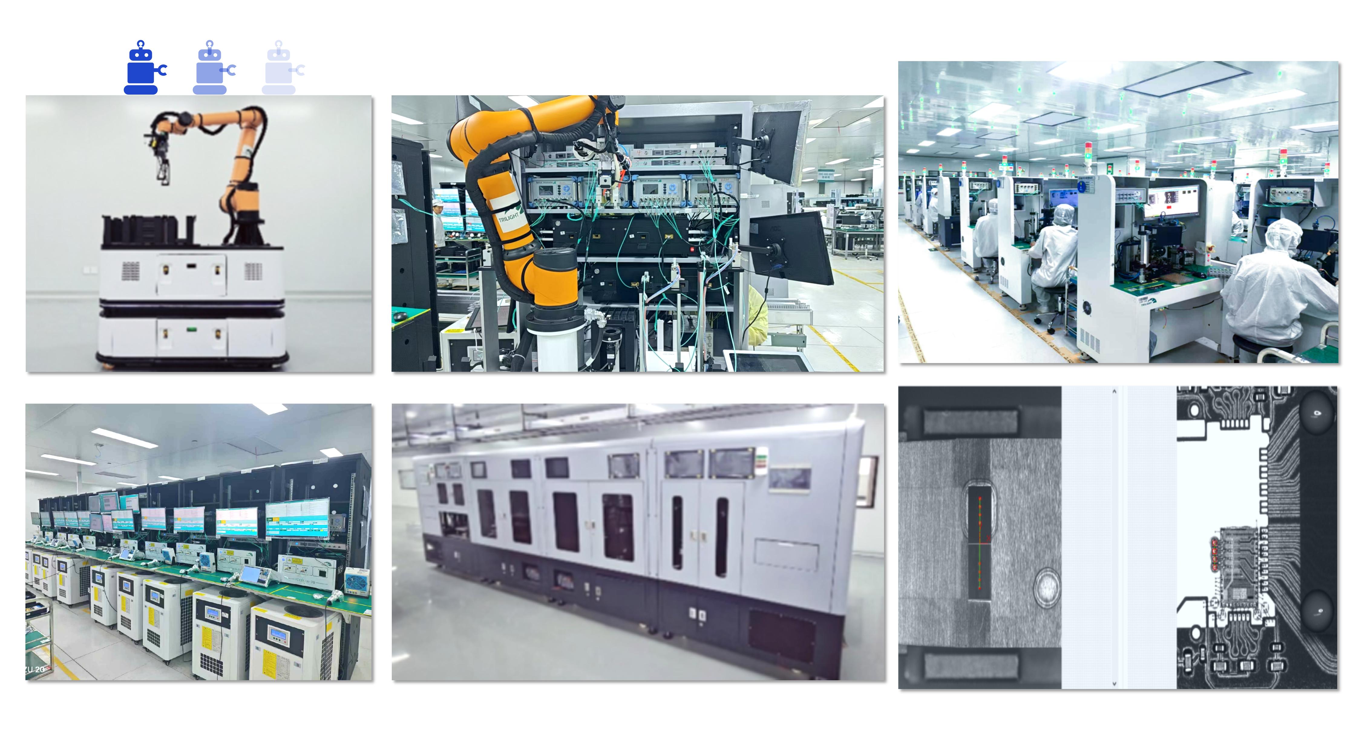
Processing and Manufacturing
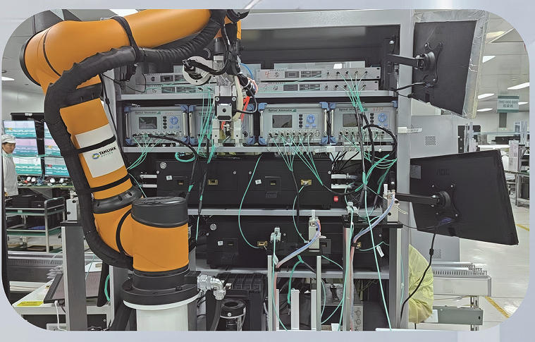
Fully self-developed coupling automation equipment and tri-temperature test stands, enabling flexible monthly capacity allocation and high production yields.
Tanlink Optics Automated unmanned workshop
Step 1 Optical Engine Desigh & Production.
The optical engine is seen as the core optical component in a transceiver. The optical engine’s packaging and production are mainly achieved in automated production area through using COB (Chip on Board) technology, which comprises 3 key process: die bonding, wire bonding and coupling .
Step 2 Transceiver Assembly
All finished optical components need to be packaged in the transceiver housing. This step is often finished in the manual production area.
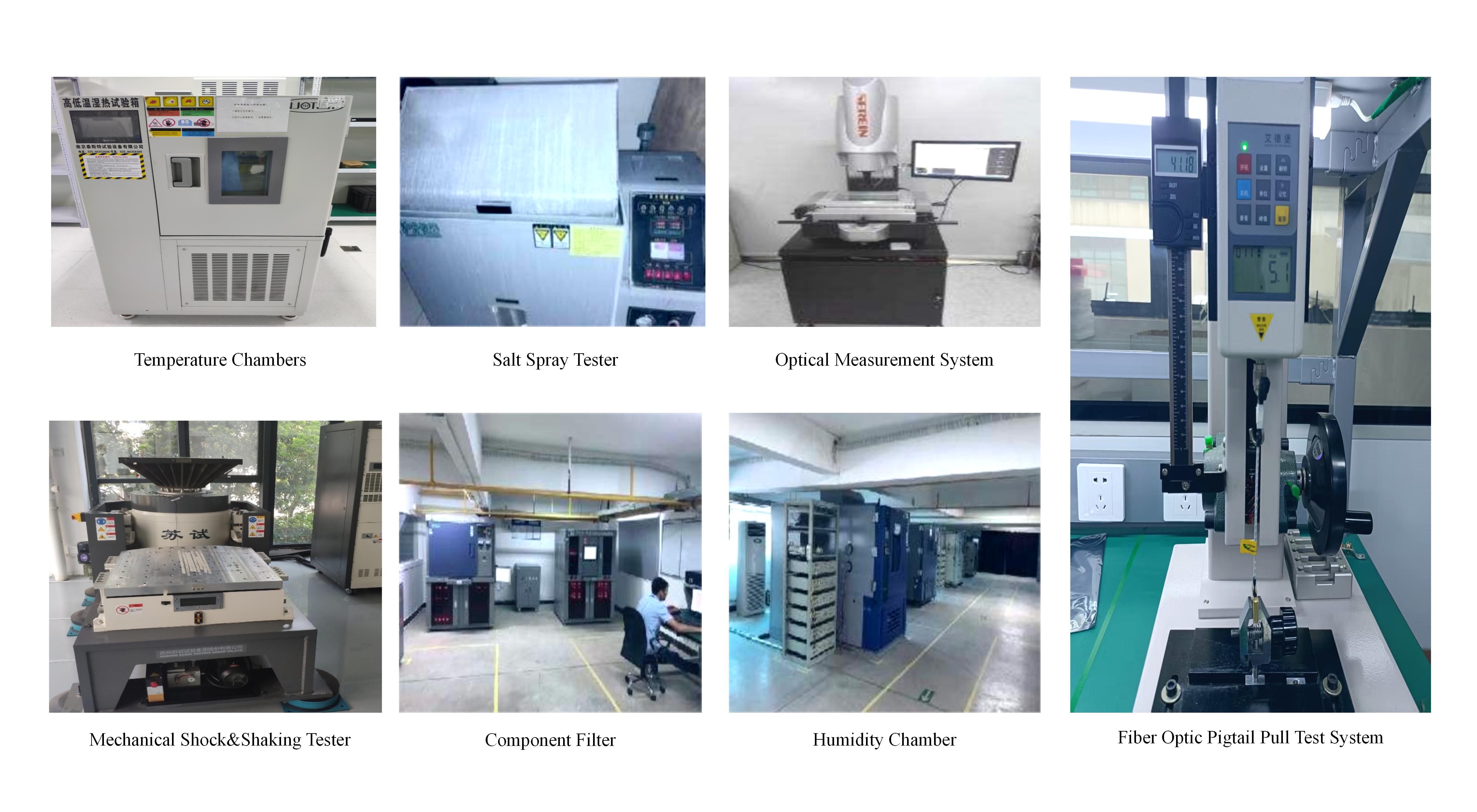
.Step 3 Testing
In the test area of Tanlink's factory, each transceiver must be tested to make sure whether it is in line with the corresponding standard. Additionally, each one must be determined whether it can resist extreme environments and circumstances.
Temperature & Humidity Cycling Test
Temperature & humidity cycling test is used for examining the ability of
Tanlink's transceiver products to resist extremely low and extremely high temperatures and humidities.
Vibration Test
Vibration test is for determining whether our transceiver products can withstand
various environment vibrations by simulating possible vibration environments encountered
by the product in the process of transportation, installation and use.
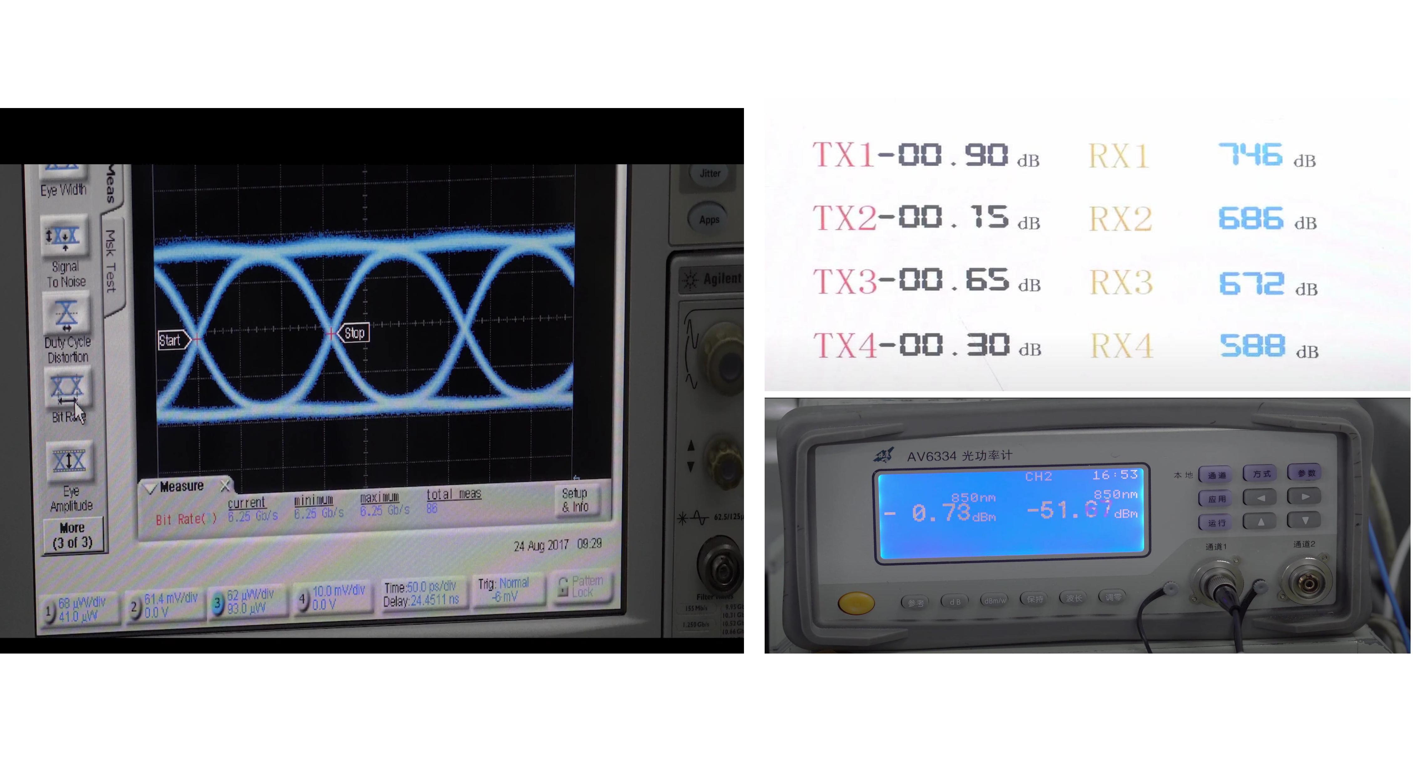
Performance testing
involves in a ser- ies of metrics including eye diagrams, receiving sensitivity,extinction ratios,
signal-to-noiseratio, bit error rate and spectrum test, etc.
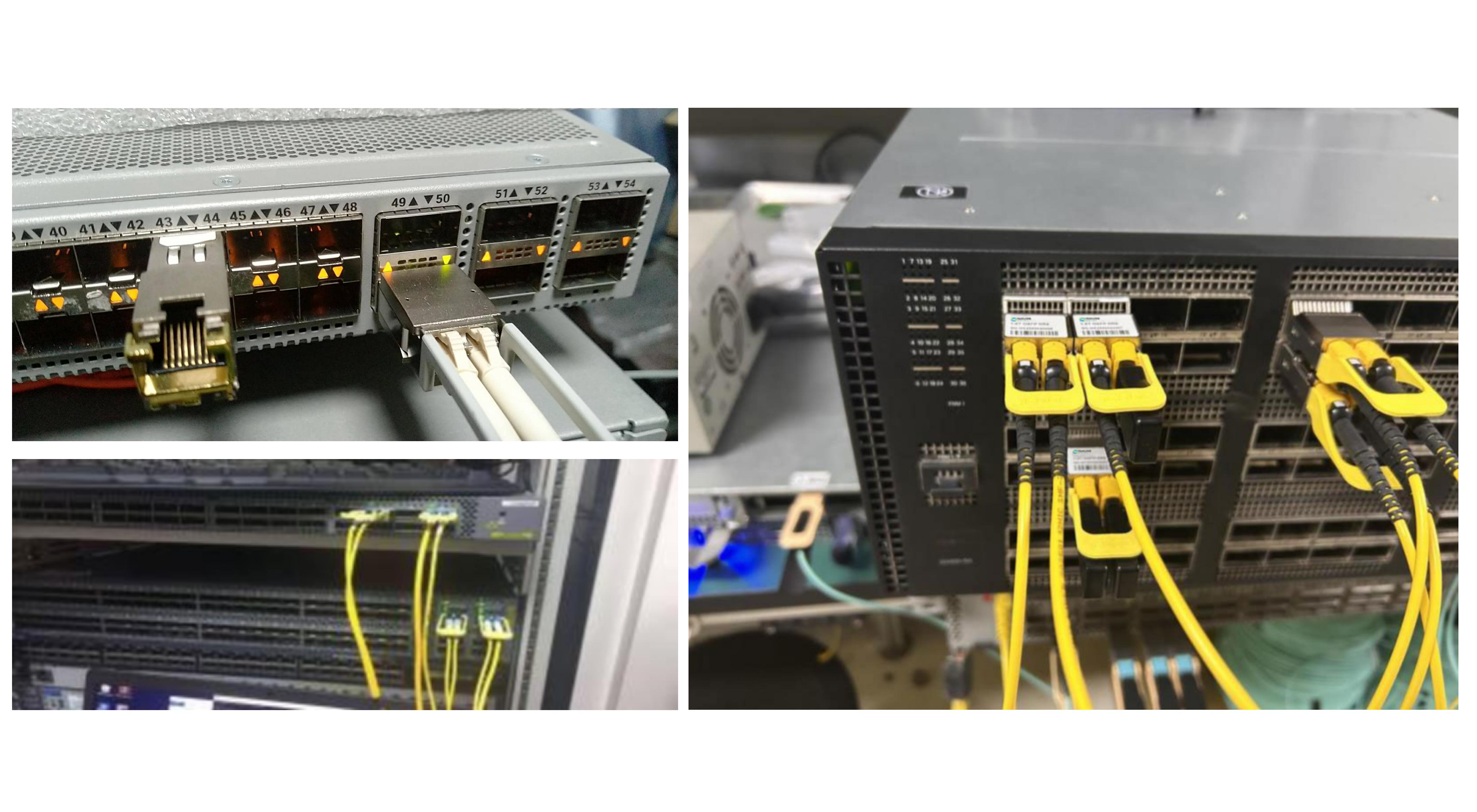
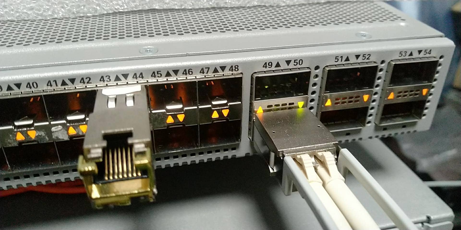
Before delivery, each transceiver will be tested in a simulated OEM environment to make sure our transceivers are fully compatible with OEM systems.
Test Equipment such as:
MGMT AIS800-64O MGMT AIS800-64D
Mellanox SN2700
CISCO N9K-C93180YC
Cisco C8111 N9K-C93180YC-EX
ARISTA 7050Q-16 DCS-7050CX3-32S-F DCS-7060DX4-32S-F
Nvidia QM9790 SN5600 CX7 QM8700 Quantum-X800 Q3400-RA 900-9X81E-00EX-STO MCX75310AAS-NEA MCX715105AS-WEAT
DELL Z9432-ON (400G QDD)
Juniper QFX5220-32CD
Nokia 7250 IXR-e
Keysight N5227B Vector Network Analyzer